BPC PowerMaster Owner's Manual Page 12

  • Download
  • Add to my manuals
  • Print
  • Page
    / 16
  • Table of contents
  • BOOKMARKS
  • Rated. / 5. Based on customer reviews
Page view 11
12
Configuring your LCS Device
T
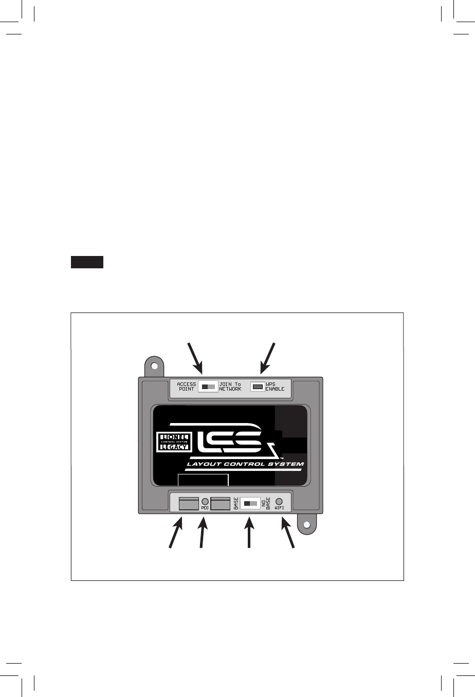
he illustration below shows the name and location of each switch, connector and indicator
light on your LCS WiFi module. The function of each is described on following pages.
A – ACCESS POINT or JOIN To NETWORK switch
B – WPS ENABLE pushbutton
C- LCS PDI cable input—use either connector.
D – Red PDI Activity Indicator
E – BASE or NO BASE switch
F – Green WiFi Activity Indicator
Lionel highly recommends using ACCESS POINT mode and manually switching
between your WiFi layout control connection or your internet access connection.
When using “Join to Network” mode, you will experience control lags due to latency
in the network when the network has heavy traffic.
Figure 8. WiFi callouts
Note!
LCS PDI CABLES
use either connector
WiFi
6-81325
A B
C D E F
Page view 11
1 2 ... 7 8 9 10 11 12 13 14 15 16

Comments to this Manuals

No comments